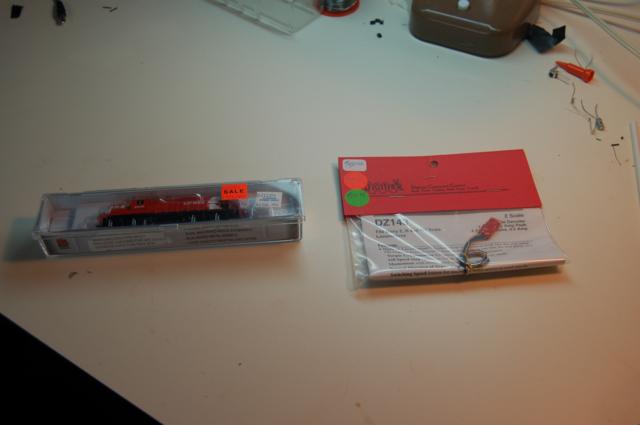
Installing a DCC Decoder in a Life Like GP9u/p
 |
Installing a DCC Decoder in a Life Like GP9u/p |
The conversion of my layout to DCC from cab control required me to put decoders in each of my locomotives. Now many of my locomotives had drop-in light board replacement boards, so the conversion was simple and only took a couple of minutes. This was not the case with my Life-Like chopnose GP-9's. For these I needed to install wired decoders. This process is fairly easy if you're patient and careful.
The materials you need are:
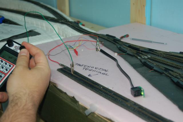
| Step 1: Use the decoder tester to test the decoder to ensure it works. Digitrax decoders are set to two-digit address 03 at the factory, so if you're using a new decoder, this is important to remember. |
 |
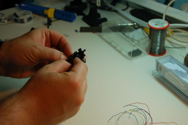
| Step 2: Carefully remove the shell of the locomotive. The walkway will come off separately from the shell, remember to disconnect the handrails from the cab before you do this. You can also remove the trucks at this point. |
 |
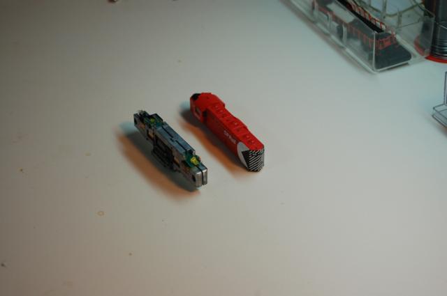
| Step 3: With the shell and trucks removed, mark the front end of each frame half so you remember which end is which. |
 |
| Step 4: Remove the screws and nuts that hold the two halves of the frame together. |
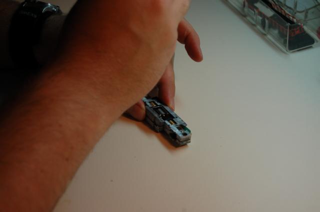 |
| Step 5: Before removing the motor, mark the top so you know which side is up. |
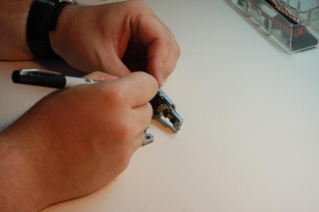 |
| Step 6: Remove the motor and motor mount from the frame. |
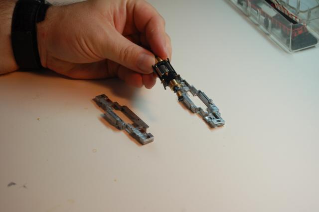 |
| Step 7: Remove the mount from the motor. |
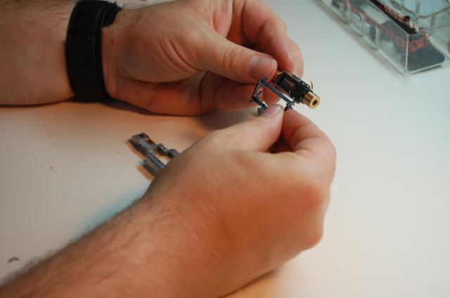 |
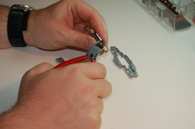
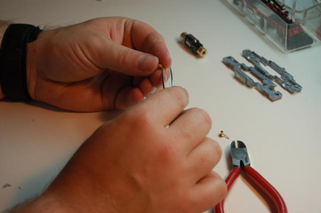
| Step 8: Carefully remove the top brush cap. It is important to do this carefully as there is a very small spring inside the cap and removing the cap too forcefully could result in the loss of the spring. Once the cap is removed, use the tweezers to remove the spring and put it in your parts box. Also remove the brush and put it in the parts box. |
  |
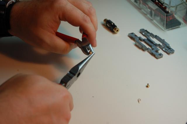
| Step 9: There is a small phosphor-bronze tab on the brush cap. Use the needle nose pliers to remove the tab. Do step 8 and 9 for the bottom brush cap. |
 |
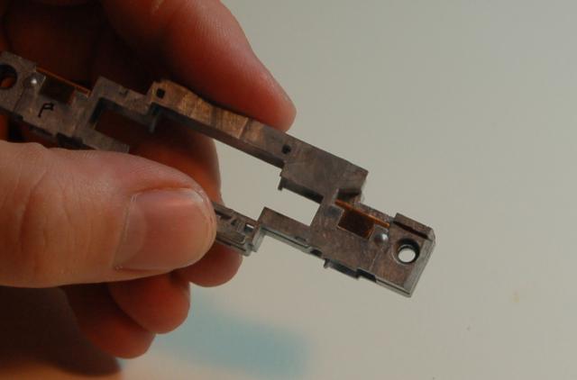
| Step 10: On the fireman's (left) side frame (the one with the bronze tabs on it) make a mark just above the bronze tab on the rear of the frame. This is the material on the left frame that needs to be removed to hold the decoder. |
 |
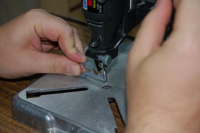
| Step 11: Using the rotary tool and the milling bit, mill away the material above the line. Safety goggles are a must here. Remember, the frame will heat up considerably during this process, so either use a vice or stop to let it cool once in a while. |
 |
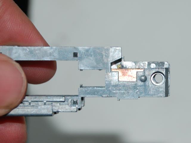
| Step 12: Line up the engineer's (right) side frame with the newly milled left side. Draw a line to show what needs to be removed. Alternatively, if you set the Dremel drill press to the proper depth at Step 11, you shouldn't need the mark. |
 |
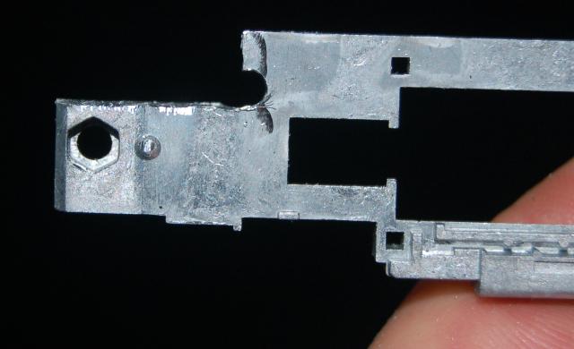
| Step 13: Mill out the right side frame rear. You will need to notch into the frame under the slots where the light board slides. |
 |
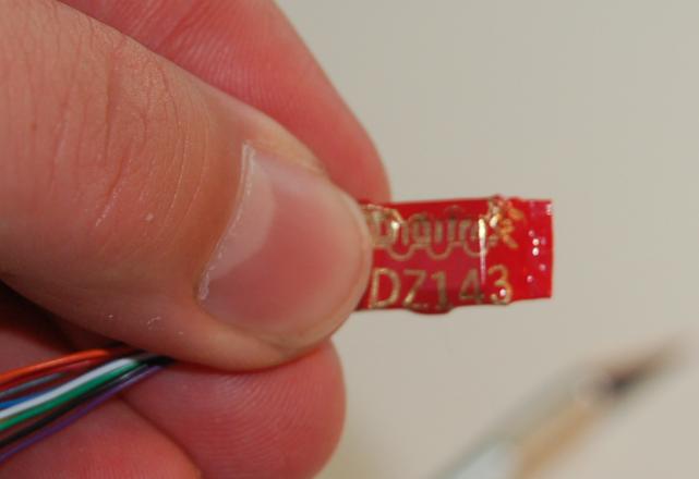
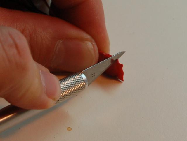
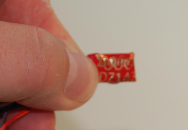
| Step 14: There is some excess heat shrink tubing on the end of the decoder. Using a sharp hobby knife carefully trim the excess from the decoder. |
   |
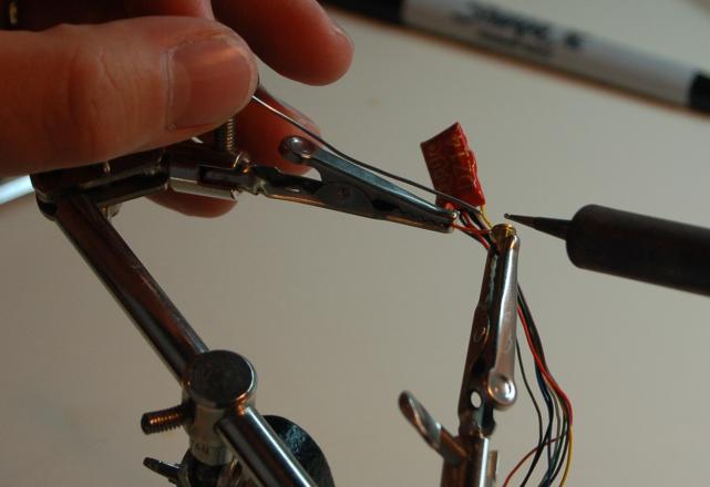
| Step 15: Measure out the distance from the back of the frame to the top of the motor brush. Cut the orange wire to this distance. Solder this wire (orange) to the groove around one of the brush caps. |
 |
| Step 16: Measure out the distance to go from the back of the frame to the bottom motor brush. Cut the gray wire to this distance. Solder this wire (gray) to the groove around the other brush cap. |
|
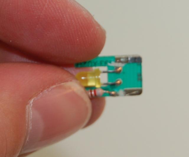
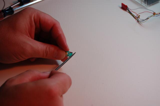
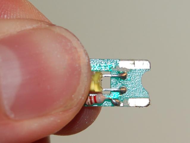
| Step 17: Take the rear light board (see photo) and using a sharp hobby knife cut the trace between the silver pads and the LED and resister leads. |
 |
| Step 18: Use the rat-tail file to make a notch in the end of the rear light board. This is to let wires through. |
  |
| Step 19: Using a small drill bit, make two small holes at the end of the silver traces nearest the LED. |
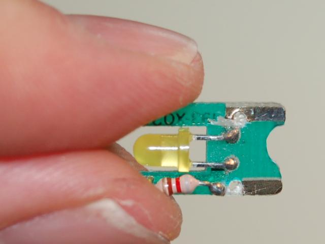 |
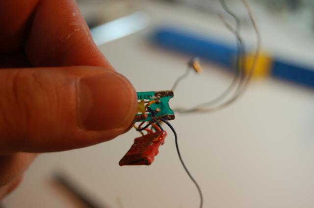
| Step 20: Cut the red, black, blue and yellow wires to about 1.5cm long. Solder the red wire through the hole you made in step 18 in to the right silver trace (the right side is the one, with the traces pointing up and the LED pointing to you). Solder the black wire through the other hole to the other silver trace. Next solder the yellow wire to the end of the resistor closest to the silver traces. Solder the blue wire together with the leftover blue wire from when you cut it, to the left side of the LED. |
 |
| Step 21: On the front light board, remove the silver traces completely, up to the leads of the resistor and LED. |
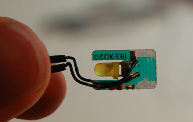 |
| Step 22: Measure the distance from the back to the front light board, cut the white wire from the decoder, and the blue wire you attached to the rear light board to this length. Solder the blue wire to the end of the resistor closest to the removed silver trace. Solder the white wire to the LED lead farthest from the resistor (This is opposite of what is in the photograph, whoops!) You can now cut the green and purple wires off at the decoder, they will not be needed. The decoder is now fully wired. |
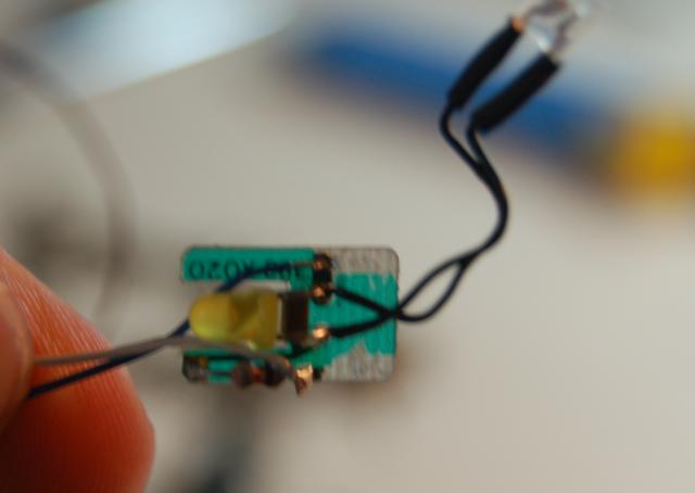 |
| Step 23: Return the brush to the top of the motor. Insert the spring into the brush cap connected to the orange wire then return the cap to the motor. Do the same for the bottom with the cap connected to the gray wire. |
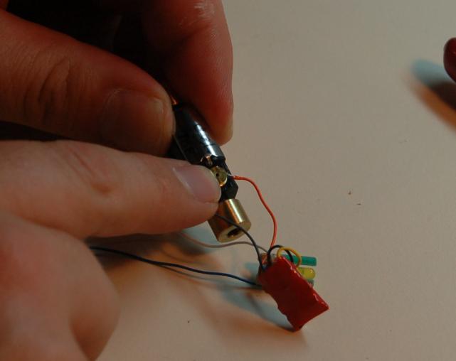 |
| Step 24: Place some kapton tape on the brush caps to make sure they are insulated from the frame. |
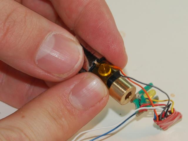 |
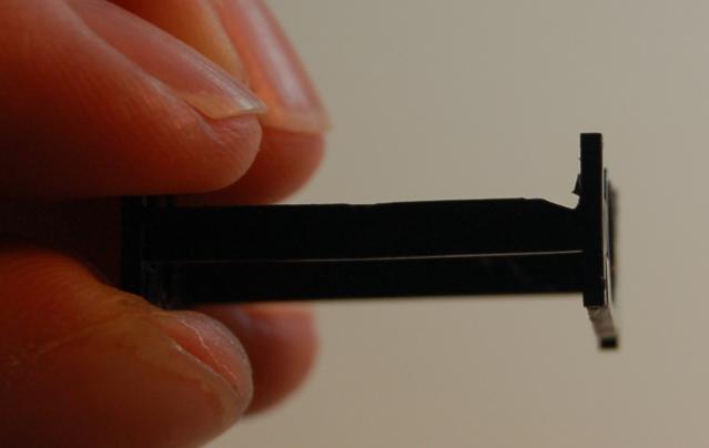
| Step 25: Make a notch at the top rear of the motor mount to allow the motor wires to feed through it. |
 |
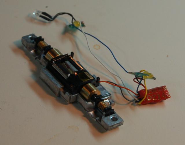
| Step 26: Re-install the motor and gears. |
 |
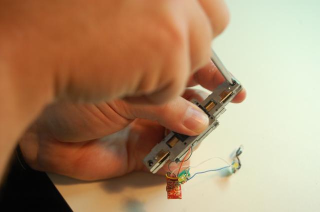
| Step 27: Put the frame halves back together. Remember the insulating washers between the two frames. |
 |
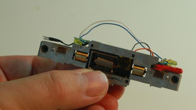
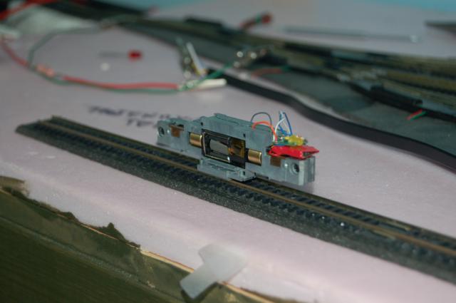
| Step 28: Put the decoder and two light boards into the frame as shown in the photograph. |
 |
| Step 29: The setup can be tested by carefully placing the frame on the track so that one side is resting on one rail and one on the other. If when you put the frame on the track you hear noises from the decoder, or the short warning beeps from the command station, remove the frame from the track IMMEDIATELY. Check for shorts, especially around the light boards, then try again. |
 |
| Step 30: If there are no shorts, test the unit by running the motor and turning the lights on and off. If the motor runs and the lights don't light, you may have the lights hooked up backwards (LED's only work if the current goes the correct way). |
|
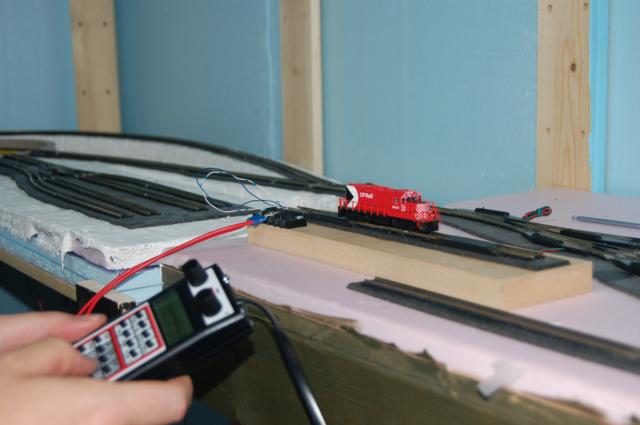
| Step 31: Replace the hood, electrical pickups walkway and trucks. Test the engine again. |
|
| Step 32: To the programming track and set up the locomotive address and any other CV's you want to adjust. |
 |